360 Degree Docking
This page is useful to owners of the Jeanneau 360 degree Docking System and the Beneteau 360 degree Dock and Go System
Scroll down for Problems and Fixes
Introduction
Welcome to this 360 Degree Docking System User Page!
I am the proud owner of a Jeanneau 49i which I launched new in August 2011. Her name is Mystique I (roman numeral for 1) and she is fitted with a ZF360 Degree Docking System. In some markets this system is called a ‘Dock and Go System’.
This is a fantastic innovation from the Beneteau and Jeanneau factory in collaboration with ZF, Yanmar, Glendinning and others. Basically the system allows a user to move the yacht in any direction, including sideways. This enables the skipper to berth his yacht in tight spaces in light to moderate current and wind direction and strength. Once the wind is above 25 knots (strong wind warning) you need to be able to draw upon traditional boat handling skills. Normally if there is a strong wind warning most of us would not go out anyway.
The system relies on integration between the Joystick, Throttle Head, Autopilot, Bow Thrusters and various parts of the diesel engine including the Throttle actuator and the Drive Leg.
In the first few years of ownership I did have a few problems with the system. I must say that ZF and Jeanneau looked after me extremely well and all issues were resolved in a very timely and professional manner.
For the past 2 years I have experienced excellent reliability and have had just one issue relating to the 12 volt power supply from the House and Start battery banks. Again with assistance from ZF and Jeanneau I have found the fault and solved the problem.
I have been sailing since 1983 and happen to also be an electronics technician. I like to fix things myself so that in the event that I am cruising in a remote location and I experience a failure I can fix it. Therefore I have equipped myself with onboard spare parts, technical information, parts lists and support contacts etc. It is also possible to purchase from ZF a diagnostic harness and software which could save a lot of time in isolating the cause of a fault in the system, especially when a serious fault in the system results in the default shutdown of the ZF system.
There are not many of these systems in Australia but I understand that worldwide there are about 400 users.
I have posted below details of any problems I have had in the past or problems that have occurred on other vessels and what has been done to fix each problem. I hope that this will assist other users who might experience a system failure or who would like to be prepared with spare parts and resources in case of a failure.
If I can be of any assistance please contact me on +61 418 243 042. Please SMS me with your email address if I do not answer and I will get back to you.
Barry Barnes
S.V. Mystique I
Problems and Fixes
FAULT 1
Intermittent or consistent error state indicated by flashing red led on joystick when docking system is engaged. In most cases, the system disengages the drive propulsion and engine revs are reduced to idle.
Possible causes:
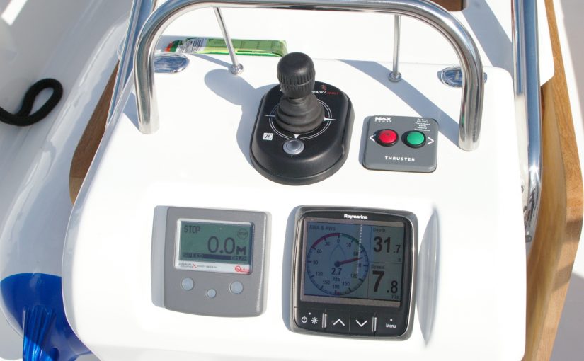
Joystick failure
Possible if you have not previously replaced your original joystick and it has a silver button as shown in the picture above. Joysticks with a black button, installed from May 2013, should not fail. The serial number of a joystick that I know to be reliable is 3329 217 148 10. If your serial number is higher than that it should not fail.
- Replacement joysticks can be purchased from your nearest ZF service agent. Here are a couple of website addresses for ZF:
- www.zfmarinepropulsion.com (USA)
- www.zf.com (Australia/Asia/Pacific)
Throttle Engaged
- The Throttle should be in the neutral (vertically up) position when you engage the Docking System.
Rudder Not Centered
When you engage the Docking System, it uses the autopilot to centre the rudder. If the autopilot is not turned on or it takes too long to centre the rudder, the system will go into an error state.
- Make sure the Autohelm is switched on at the switchboard (in Standby).
- Do not leave the rudder at full lock when engaging the Docking System.
- Remove/fix any physical impediment to the rudder being centred.
FAULT 2
You engage the Docking System and everything seems to be working. Half way through the docking manoeuvre the bow thruster stops working but the drive leg still works. This is apparent when moving the joystick directly to starboard or port.
Bow Thruster Relay Contacts Intermittent
On my vessel the MAX Power bow thrusters operate with a 24 Volt DC power supply. The battery bank is made up of four twelve volt batteries. When you are not using the bow thrusters these batteries are connected in parallel and charged by one of the battery charger’s 12 Volt DC outputs or directly from the Engine alternator via a charge distribution box. You can test the bow thrusters by dis-engaging the docking system and engaging the bow thrusters using the two button bow thruster control panel.
When you engage the bow thrusters a relay connects the batteries into series parallel where the output voltage becomes 24 Volts DC. This is to reduce any voltage drops in the circuit to the bow thruster motor. The Bow thruster motor draws several hundred amps when energised. At 12 volts, twice the current would flow to provide the same power to the bow thruster props.
- The relay box can be dis-assembled and the relay contacts cleaned up carefully with an abrasive such as wet and dry abrasive paper.
Bow Thruster Control Circuit Wiring Connectors Loose
It is possible for the wiring connectors to fall off as a result of the vessel pounding in a sea. In my vessel one control wire connector came completely off it’s mating contact.
- Pull a little length of the wire through the wiring loom to ensure that there is no physical strain on it and re-connect.
Bow Thruster Control Panel Faulty
The two button control panel can fail, especially if exposed to moisture.
- Replace the two button control panel.
- Supplier: www.max-power.com
FAULT 3
The Docking System is not engaged. The Throttle lever is in any position. Engine speed changes and drive engages or disengages without manual command or control.
Throttle Head Unit Faulty
The throttle head unit is normally very reliable. However, if the drain hole at the bottom of the unit is physically blocked, moisture can be trapped inside the unit and it can fail as a result.
- Stop the engine. This might entail holding the engine stop button for several seconds if engine revs are high as a result of the error.
- Replace the faulty Throttle Head Unit.
- Supplier: ZF.
FAULT 4
With the Docking System engaged or disengaged, forward or reverse drive cannot be achieved by moving the Throttle Lever in the Cockpit.
Throttle Actuator Faulty
The ZF Throttle Control Head engages the drive via the Throttle Control Actuator. This part is manufactured by Glendinning in the USA. In one case that I am aware of this fault was caused by a coil which became electrically disconnected from the control board that it was mounted on. This was repaired with a soldering iron by re-connecting the coil to the printed circuit board.
Check the voltage at the input to the Throttle Control Actuator. It should be between 1 and 4 volts when the throttle lever is pushed to the forward position with the engine running. If there is no voltage then the fault is in the Throttle Head Unit or the wiring from it. If there is a voltage between 1 Volt and 4 Volts (should increase from 1 Volt when the Throttle Control is moved forward) then the Throttle Control Actuator is suspect. If the input voltage is zero then the Throttle Control Actuator is most likely not to be faulty.
- If input voltage appears correct, replace the Glendinning Throttle Control Actuator Unit.
- Supplier – www.glendinningprods.com
FAULT 5
With the Docking System disengaged and the Throttle in forward propulsion position at cruising speed, after a few seconds or several hours the propulsion disengages and the engine revolutions reduce to idle.
This should happen whenever there is a serious fault in any components of the docking system. If you have purchased a diagnostic wiring harness and software from ZF you can more quickly isolate the issue. I experienced this symptom and at first looked for a problem in the Throttle Control Actuator. To ascertain whether the Docking System has engaged this safety feature as a result of a serious Docking System component fault, check the voltage at the input to the Glendinning Throttle Control Actuator. If there is no voltage then the system has probably detected a serious fault in one of it’s components. If a voltage between 1 volt and 4 volts is present then this would indicate a fault in the Throttle Control Actuator.
When I experienced this fault condition, the cause was in the 12 Volt battery supply to the Docking System.
- Check the 60 Amp fuse which supplies power to the VMU. I replaced this fuse. It was not blown but showed signs of corrosion.
- Check all 12 volt connections, including battery terminals, protection circuits, switches etc. for signs of corrosion and proper tightness.
- Isolate non-associated electrical loads and test the system.